
Geometry (Pre-Process)

Figure 1:Geometries of Test Aerofoils, (a) NACA 0012 (b) Flat Plate and (c) Curved Plate
|

Table 1:Specifications of the Aerofoils
|
The aerofoil shapes are shown in Figure 1 and their specifications are shown in Table 1. The chord length [1] is referred to as the straight line between the leading edge and trailing edge. The thickness ratio means the ratio between the aerofoil thickness and the chord length. Camber ratio means the ratio between camber length [1] and chord length.
The three geometries are set in the different angles of attack from 2° to 7° with an interval of 1°, which means totally 18 models have been simulated.
The three geometries are set in the different angles of attack from 2° to 7° with an interval of 1°, which means totally 18 models have been simulated.
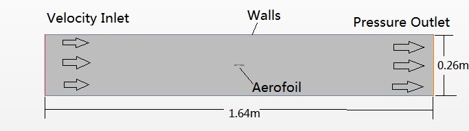
Figure 2:The Flow Region
The aerofoil is placed in the centre of the flow region and the flow goes in from the left-hand side and goes out from the right-hand side (Figure 2). The dimensions of the flow region have been minished to simplify the simulations and save the computational resources.
Reference
[1] Douglas, Gasiorek and Swaffield. (1995). Effects of compressibility. Compressible Flow around a Body. Fluid Mechanics. 3rd edition. New York: Longman. P395-400
[1] Douglas, Gasiorek and Swaffield. (1995). Effects of compressibility. Compressible Flow around a Body. Fluid Mechanics. 3rd edition. New York: Longman. P395-400
