
Experiment
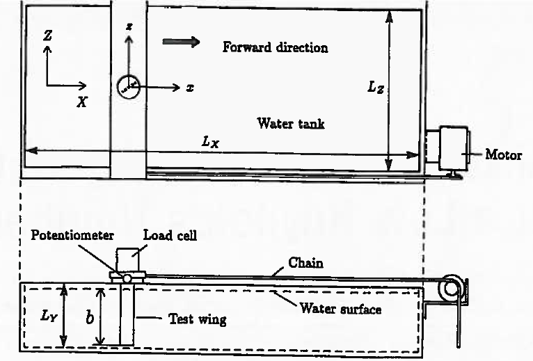
Figure 1:Experimental Apparatus and Arrangements
|

Table 1:Dimensions of the Water Tank

Figure 2:Three Aerofoils Used in Flow Visualisation
|
The experiment about aerofoil characteristics has been implemented by Shigeru Sunada et al [1]. In this project, the analogous numerical simulations were done using the CFD methods.
In Figure 1, test wings are mounted on the loading cell which is towed from the left side to the right side. The loading cell is used for measuring the hydrodynamic forces on X and Z directions (drag and lift forces respectively). The relative speed of water in the tank is about 0.12 m/s, which ensures that the Reynolds number is about 4,000.
For the wings tested, three aerofoils (Figure 2) were chosen to make the flow visualisation by the floating aluminium dust on the water surface. All the wings have the same chord length, c=40 mm and the same span length b=270 mm (b is indicated in Figure 1). Other specifications of aerofoils are mentioned in Pre-Process (Geometry).
Reference
[1]S.Sunada, A.Sakaguchi and K.Kawachi. (1997). Aerofoil Section Characteristics at a Low Reynolds Number. Journal of Fluids Engineering. 119, p129-135.
[1]S.Sunada, A.Sakaguchi and K.Kawachi. (1997). Aerofoil Section Characteristics at a Low Reynolds Number. Journal of Fluids Engineering. 119, p129-135.
